|
|
Musician's Tech Central
Music Equipment, Recording, MIDI, Digital Audio, Indie How-To |
|
The Mixer
by Rob Sommers and Bob Steiner
MTC Editor's notes:
- Our thanks to raw42 electronic sound for giving us permission to reprint this two-part article from their Personal Studio 101 series. For those who are unfamiliar with the in-line mixing board, this article sorts out and clearly explains the various functions.
- The authors own Work Audio studios in Cleveland, Ohio, a central point for electronic music recording in the region which also handles audio and custom music for local indie films and corporate production houses.
Part I
Our topic of choice this month brings us to one of the most important elements in the personal studio, that of the mixer. Traditionally, there are two types of mixers: split-section and in-line. The split-section configuration is most common in high-end mixers (or consoles) that are not only big in size, but also big in price. These are the babies that you would find in the big commercial studios.
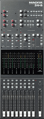
The second type of mixer, and the one we will focus on for this article, is the in-line mixer. To aid in our discussion, we will use a diagram of the Mackie analog 8-bus configuration, currently one of the most popular mixers in the personal (or project) studio.
Keep in mind, the majority of what we will describe here applies to all mixers, so most of what we present can be applied to whatever type or size of mixer you may be using. So follow along with the picture as we cover each section of the mixer channel.
XLR Input (not visible in the graphic)
This is the 3-pin microphone input on the channel strip.
1/4" Input (not visible in the graphic)
This is the "guitar chord" style connector. This input can be balanced (+4) or unbalanced (-10). This one factor alone can create its own topic for debate. Some claim balanced is better because it’s the "professional's" choice, whereas unbalanced inputs are geared more towards "consumer" gear. It really does break down to what is best for the specific equipment being used and the circumstances involved.
Tape Input (not visible in the graphic)
This input is similar to the 1/4" input but is fed into the mixer via a separate signal path. This would allow you to have, say, 24 tracks of ADAT outputs hooked into the mixer while at the same time, having 24 outputs of electronic gear hooked up. This would cut down, or hopefully, eliminate constantly re-patching things into the mixer. 
Gain
The gain (or trim) knob is typically located at the top of the channel strip. It allows the user to boost the level of the sound source (microphone, keyboard, sampler, etc.) to a typical line level. The gain is usually adjusted via a rotary trim potentiometer like the one in the picture. This is where the term "gain pot" or "trim pot" comes from - it's short for potentiometer.
The gain knob is actually controlling the preamplifier in that channel and that pre-amp is what is actually boosting or increasing the level of the signal. It is important to implement good gain structure when using any mixer. This will maximize your signal to noise (s/n) ratio and keep your audio as "clean" as it can be.
Auxiliary Sends
Most mixers now have at least 4 auxiliary (or aux) sends. This allows each channel to send signal to an effects processor (reverb, delay, distortion, etc.) that has been patched into the appropriate auxiliary send. This is very common in both sound reinforcement and in the mixing process. The auxiliary sends are also commonly used for feeding a headphone mix during recording, or for feeding stage monitors for performing musicians in a live setup. This allows the engineer to designate two sends (for example 1 & 2) to provide a separate mix for the performers. These sends that feed the inputs of different effects are usually brought back into the mixer via the mixers effects return section or into empty channel inputs.
Equalization
The equalization (or EQ) section in every mixer is divided into three main frequency spectrums: low, mids, and highs. This gives you the ability to increase (boost) or decrease (cut) a frequency or frequency range by a number of dB. The low cut button provides a steep drop off of low frequency content. This frequency range is usually 75-80 Hz and below. This usually takes out room rumble and air movement noise. It is commonly used in vocal EQ'ing.
The "EQ In" button is depressed in order to actually activate the EQ section of that channel. Also, in keeping with the cleanest signal-to-tape/less-is-more approach, you may want the signal to internally bypass the entire EQ section which, in theory, will eliminate any noise that the EQ section may add and allow you the cleanest path to your mixer's outputs.
Mix B
Mackie refers to the second portion of their in-line mixer as Mix B. Mix B allows for 2 signals to share the same channel strip but only allows one of the two sources to have EQ and auxiliary send capabilities. The Mix B section of the Mackie 8-bus does allow for panning and has a volume knob that replaces the fader on the main fader section. Also, the flip switch allows the user to assign which section (a or b) gets use of the EQ portion of the channel strip.
Pan
The pan section of the mixer is usually the easiest to explain. It allows the user to place the sound source in the stereo field, from extreme left to extreme right in non-surround sound applications. The role of the pan knob will be further discussed in the group/buss assignment section.
Solo
The solo button allows the engineer to listen to one sound (or track) at a time. Sometimes while listening to a mix, it becomes essential to be able to single out a sound and listen to it individually in order to further adjust it. It is also often used during a large mix where you may have so many sounds that it becomes hard to recall by memory sonic differences between backing vocal 6 and backing vocal 7. The solo button is one of the engineer's best friends.
Mute
The mute button allows the engineer to quickly and easily mute whatever is on that channel. The mute button silences the audio throughout the channel path (i.e. mutes the aux sends, EQ, channel, and buss section).
Group/Buss Assignment Buttons
This allows the engineer to direct the sound to whichever group output he desires. Many times, engineers will "group" together instruments. For example: group 1 & 2 (1 = left, 2 = right) could be all drum and percussion sounds; group 3 & 4 guitars; group 5 & 6 synths and samplers; and group 7 & 8 vocals. While mixing, this allows the engineer to very quickly cut and boost entire instrument groups instead of having to do each one of them separately.
During tracking or recording, the group/buss assignments are used very differently. For example, if we have a vocal mic plugged into channel 32 of our mixer, we can route that signal to buss 1 by simply panning that left and assigning it to groups 1 & 2. But by panning it, we have only sent it to buss 1 (again 1 = left, 2 = right). Once it is time to move onto track 2, we simply pan it hard right and we are now ready to record on track 2 via buss 2. This arrangement allows for very fast reconfiguring of the board during the recording process. But also note that, in this case, the Mackie 8-bus has only 8 busses, making them redundant in an effort to feed a 24 track recorder (analog or digital). In other words, the mixer may have 24 outputs, but buss 1 is mirrored by tracks 9 and 17, buss 2 is mirrored by tracks 10 and 18, and so on.
L/R Mix Button
This button assigns the signal to the master left/right (L/R) section of the board. This is the easiest way to get signal to the outputs without having to group them to separate busses. For example, during vocal tracking, the L/R usually would not be pushed as the engineer would assign the vocals to a buss to go to tape and then actually monitor back off of tape. So the mixer channel that has the tape outputs coming into it would be assigned to the L/R mix section and not the actual channel with the mic plugged into it. The reason being is that it allows the engineer to monitor what is coming back off of tape so he can check levels and verify the quality of the recording.
Fader
This is the volume control for the channel strip. It allows the engineer to very easily and graphically see and change the mix. Next to the panning knob, this is probably the most intuitive of all of the components on the mixer.
What's Next?
[In Part II] we'll cover the master section of the mixer as well as some of the more common connections on a mixer's output section. If we've confused you at all, or maybe you just can't believe how easy we made that sound, drop us a line at malignant@bigfoot.com. Later...
Part II
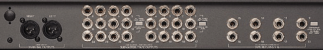
[In Part I] we started our coverage of the in-line mixer by explaining the channel strip most commonly found on these types of mixers. As promised, this month brings us to the conclusion of the in-line mixer by explaining the master section. To better illustrate this master section, we will again be using the Mackie analog 8-bus for our example.
Nearly every mixer’s master section is similar, with a section of group outputs and a master left/right section. Keep in mind, the majority of what we will describe here applies to all mixers, so most of what we present can be applied to whatever type or size of mixer you may be using. So just follow along with the pictures as we cover each part of the master section.
The master output section of the Mackie 8-bus is divided into 9 major sections as follows:
 AUX Sends AUX Sends
This is how you feed your effects units. The six auxiliary sends each have a master send pot. The output of each send is available on the AUX Send Out jack in the panel above the master section. AUXes 1 & 2 are balanced outputs. Additionally, AUX Sends 3 & 4 and AUX Sends 5 & 6 are fed as stereo pairs to the two Phone Source switching matrices for headphone cueing purposes. The AUX Solo buttons allow the engineer to solo or only hear what is being fed to the auxiliary send. Depressing these solo buttons also allows you to see your level on the main meters. All of the AUX Sends are 1/4" connections.
Stereo AUX Returns
This portion of the mixer is where the effects processors are returned back into the inputs marked AUX RETURN 1-6. Typically, these returns will have a solo button, a pot for level control, and pan pot for panning ability. Returns 3 & 4 on the Mackie can also be assigned to several different destinations including the headphone sends and the L/R mix output. All of the AUX Returns are 1/4" connections.
Mix-B/Monitor
Mix-B level control is your master gain control when building an independent mix for recording, stage monitors, or broadcast. The Mix-B to L/R switch is essential to doubling your Ins/Outs during mixdown. When pressed, Mix-B is assigned directly to the L/R mix bus. It can also be assigned to the control room.
Phones 1 / Phones 2
In the case of the 8-bus console, these two headphone sections are completely independent of each other. Likewise, either headphone section can be fed by various sources including the monitor, Mix-B, AUX Sends 3 & 4, AUX Sends 5 & 6, and external sections. The headphone outputs are handled by stereo 1/4" (tip/ring/sleeve) headphone style connectors.
Monitor
Control room and studio playback monitors are both controlled from this section via individual stereo level controls. Any combination of sound sources can be monitored (or "listened to") at once. A MONO switch is provided to check your mixes for phase problems and compatibility with mono systems. The studio outputs on the Mackie are 1/4" connections as well as 1/4" jacks on the control room and Mix-B.
Solo
This level control allows you to set the overall volume of all the solo switches on the board.
Talkback
This section allows the engineer (or user) to talk directly (with the help of a built-in mic) to a variety of sound sources.
Meters
The meter section of any board is ultra useful. This allows you to visually see where your levels are at any given moment. The 8-buses that we talked a bit about last time are numbered from left to right 1-8, 9-16, and 17-24. This is a common practice in mixing boards, and on the Mackie is referred to as "triple busing". The MAIN meters also double as your SOLO level meters any time a SOLO button is pressed.
Group Faders
These are faders that control your group outputs. Each bus can be soloed as well as assigned to either the L/R mix in stereo or in mono. In a typical recording situation these faders are controlling the amount of signal that is sent to tape. Much like the AUX SEND masters, these faders are the last place for the engineer to make any volume changes before sending the signal to tape or to the house public address system. The Left/Right MIX bus is typically set up to feed a two-track recorder such as a DAT deck or a CD recorder. One stereo fader controls both the left and the right levels. The group outputs (buses 1-8) are all 1/4" connections. The submaster (or tape outputs) are also on 1/4" connectors as well. The main outputs are on balanced XLR connectors as well as 1/4" connectors to provide for a wide range of options for the end user.
Keep in mind that the connectors on the Mackie are similar to most project studio size mixers, but there is some variation from manufacturer to manufacturer. If you desire or require certain connection options, check out the piece of gear yourself or refer to the wealth of on-line documentation.
That’s it. Hopefully this has helped take away some of the mysteriousness of the in-line mixer for those of you who have seen these beasts in magazines and in your local music store but haven’t mustered up enough nerve to actually mess around with one. As usual, if you have any questions about this article, please feel free to contact us at malignant@bigfoot.com . Later...
Copyright © 2024raw42 music
All Rights Reserved
Back to Top of Page
|
|